+971 50 217 6793 Abu Dhabi, UAE info@lifeguarddatarecovery.com

What happens inside a data recovery lab?
What happens inside a data recovery lab The Science of Data Recovery What Really Happens Inside a Professional Lab When a mechanical hard drive starts emitting a rhythm of death clicks, a high-performance NVMe SSD suddenly drops off the PCIe bus, or an enterprise RAID 6 array crashes mid-rebuild, software tools like or generic file undeletion.
lifeguard datarecovery utilities are useless and often destructive. Operating on physically compromised hardware requires controlled environments, high-precision micro-tools, sub-nanometer alignment, and custom firmware overrides. Understanding what happens inside a professional data recovery lab reveals why salvaging critical files relies on cleanroom physics, hardware-level cloning, micro-soldering, and low-level firmware engineering.
Anatomy of a Data Recovery Lab Cleanrooms & Engineering Suites
A specialized data recovery laboratory is an engineering facility engineered specifically for physical micro-repairs, electronic trace micro-soldering, and low-level firmware manipulation. Unlike standard IT repair shops, a certified facility maintains strict environmental controls and hardware diagnostic suites.
Opening a hard drive in an unprotected room instantly exposes magnetic platters to airborne microscopic dust. When platters spin, a single trapped particle of smoke or dust acts like a boulder on a highway: it strikes the rapidly floating read/write head, causing it to bounce, scratch the ultra-thin magnetic layer off the platter surface, and destroy data permanently.
Particle Concentration Limits: ISO 5 standards permit no more than 3,520 particles per cubic meter (or 100 particles per cubic foot) at sizes of 0.5 microns or larger. By contrast, ambient office air contains over 35,000,000 particles per cubic meter.
Laminar Air Flow Mechanics: High-Efficiency Particulate Air (HEPA) or Ultra-Low Particulate Air (ULPA) systems pull ambient air through high-density filters, pushing continuous laminar air downward at 90 feet per minute. This constant positive pressure ensures that clean air flows outward, preventing ambient dust from entering the work area.
Electrostatic Discharge (ESD) Shielding: Static electricity can instant-fry a drive’s preamplifier chip (located inside the head stack assembly) or breach NAND flash gate oxide layers. Cleanrooms utilize conductive ESD flooring, continuously monitored grounded wrist traps, anti-static smocks, and ambient air ionizers to neutralize surface charges.
Advanced Data Recovery Hardware & Diagnostics
Professional laboratories do not connect compromised drives to standard computer motherboards running SATA or NVMe controllers. Standard operating systems expect functional hardware; when a drive stalls on a bad block, standard OS storage drivers hang, reset the bus, or send repeated reset commands that overheat and destroy failing read heads.
Labs rely on specialized diagnostic and extraction hardware:
Mechanical & Physical Failure Modes in HDDs
Head Assembly Degradation and Head Crashes:
The read/write head consists of a tiny ceramic slider housing a magnetoresistive (MR) sensor. Physical impacts, thermal stress, or mechanical wear cause the slider to lose aerodynamic lift and strike the platter surface. This physically tears the slider off the actuator arm or grinds the platter’s magnetic emulsion into fine dust.
Spindle Motor Bearing Seizure:
Modern hard drives use Fluid Dynamic Bearings (FDB) to suspend the central spindle motor shaft in oil. Hard drops or manufacturing defects cause the oil to leak or the shaft to bend, seizing the motor completely. The drive will emit a rhythmic humming or high-pitched buzz as it attempts to turn.
Head Stiction (Parking Failures):
When powered down normally, the actuator arm moves the read/write heads off the media and parks them on plastic ramps outside the platter perimeter. If power is pulled suddenly, the heads can stop directly on top of the mirror-smooth platter surfaces. Atmospheric pressure and surface tension cause the heads to stick to the platter surface a condition known as stiction.
Preamplifier Circuit Failure:
The preamplifier (preamp) is a micro-chip attached directly to the actuator arm inside the sealed drive enclosure. It amplifies ultra-weak magnetic signals captured by the read heads before sending them out to the external PCB. Power spikes or static electricity can fry the preamp, rendering the drive completely unreadable even if the external board appears healthy.
Electronic, Microcode, & NAND Flash Failures in SSDs & USBs
Solid-state drives feature zero moving parts, but their high-density semiconductor architecture introduces complex failure vectors:
Flash Translation Layer (FTL) Corruption & “Panic Mode”:
SSDs store data across physical NAND flash blocks using a dynamic mapping system called the Flash Translation Layer (FTL). The FTL maps virtual logical block addresses (LBAs) to changing physical NAND locations to ensure even wear across the drive. If power drops while the controller writes to the FTL, the mapping table corrupts.
NAND Cell Voltage Shift & Bit Rot:
NAND flash stores data as electrical charges trapped inside floating-gate or charge-trap transistors. Over time or when exposed to heathese electrical charges leak. If the charge drops below the threshold that internal Error Correcting Code (ECC) algorithms can reconstruct, read operations fail, causing bad blocks or total system lockups.
Controller Hardware Failure & Microcode Lockup:
The SSD controller is a multi-core processor running complex internal software (microcode). Thermal cycles or manufacturing flaws can kill the controller chip directly. In such cases, the media requires chip-off data recovery: desoldering each flash memory chip, dumping raw binary memory pages via hardware readers, and manually reconstructing the controller’s proprietary wear-leveling and striping algorithms in software.
Multi-Drive Enterprise Failures (RAID, NAS, & SAN)
Enterprise arrays (RAID 0, 1, 5, 6, 10, Nested RAID, ZFS pools) introduce layer-upon-layer of structural complexity:
Stale Parity & Secondary Drive Degradation: In a RAID 5 array built with drives from the same manufacturing batch, the failure of Drive 1 forces the array into a degraded state. The intense I/O stress of a rebuild often triggers read errors or complete failure on Drive 2. If Drive 2 drops bad sectors during the array rebuild, the controller’s parity calculations break down, corrupting entire file structures.
Array Metadata & Partition Header Loss: Power outages, failed RAID controller cards, or improper configuration changes can overwrite array configuration metadata (such as stripe block size, disk rotation order, and parity delay). Without this metadata, the underlying file system cannot assemble the volume.
Warning Signs: When Software Scans Risk Permanent Damage
Using consumer file-undelete software or running native operating system diagnostics on physically failing hardware can convert a highly recoverable drive into an unrecoverable paperweight.
Critical Auditory & Physical Symptoms
If a storage device displays any of the following physical behaviors, immediately disconnect power:
Clicking, Ticking, or Sweeping Noises: A repeating click-click-click sequence indicates that the drive’s actuator head assembly cannot lock onto the servo tracks (the alignment markers printed on the platters). The head sweeps across the platter surface, strikes its mechanical limit stop, and resets repeatedly. Continuing to power a clicking drive sweeps damaged, sharp head sliders across magnetic surfaces, scoring the platters and destroying data.
High-Pitched Whine or Buzzing: Signifies a seized spindle motor or head stiction. Forcing current into a locked motor overheats the drive’s motor controller chip (VCM driver) on the external PCB, burning out surface-mount components.
Thermal Hotspots or Burning Odors: Indicates an electrical short circuit on the drive’s controller board, TVS protection diodes, or internal preamp.
System-Level Indicators of Hardware Degraded Status
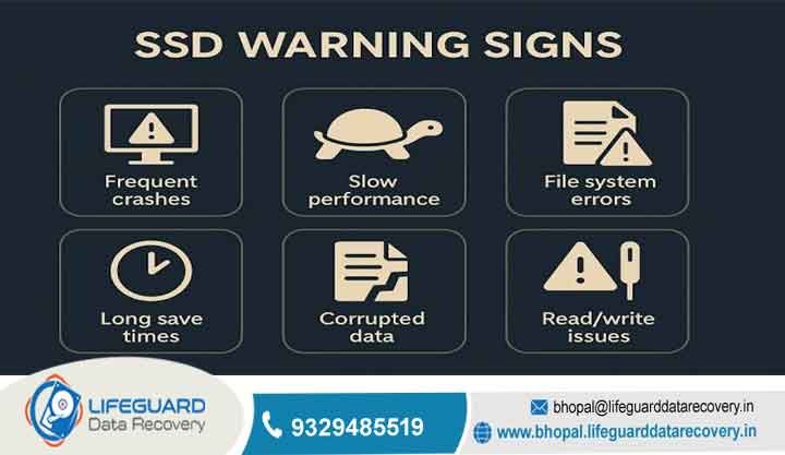
RAW File System Status: Disk Management displays the drive volume as RAW, or prompts to format the disk. This indicates that the operating system can no longer read the master boot record, GUID Partition Table (GPT), or volume boot sector due to unreadable physical sectors.
Capacity Misreporting: The drive displays incorrect capacity parameters (e.g., a 2 TB HDD showing as 0 Bytes, or an NVMe SSD reporting as 1B Diagnostic Device).
The Engineering Workflow: Diagnosis to Secure Extraction
The data recovery process inside a professional laboratory follows strict non-destructive protocols. Original patient media is preserved; engineers perform all major extraction operations on bit-stream sector copies.
Intake & Non-Destructive Diagnostics
Engineers never boot suspect drives through standard motherboard controllers. The device is routed through hardware diagnostics:
PCB Inspection: Technicians use thermal cameras and digital multimeters to inspect input power rails, check Transient Voltage Suppressor (TVS) diodes, measure sense resistors, and test motor driver ICs for electrical shorts.
Cleanroom Visual Inspection: If mechanical failure is suspected, the drive enters the ISO 5 cleanroom. Engineers open the top chassis cover to inspect platters for top-surface scoring, check for head stiction, and verify filter cleanliness.
Firmware Diagnostic Mode: The drive is connected to hardware tools like the PC-3000. Engineers power on the drive while bypassing its main application code, placing the drive into utility initialization mode. They read the Service Area (SA)—a hidden area on the platters or chip flash containing system configuration modules—to verify the health of microcode overlay modules, adaptives, and translation tables.
Cleanroom Physical Repair & Donor Matching
If the evaluation reveals physical damage inside a hard drive data recovery lab, engineers must perform component-level replacement using compatible donor hardware.
Low-Level Hardware-Assisted Disk Imaging
Once physical integrity is temporarily restored, engineers never attempt to run standard operating system file extraction. The drive remains fragile and can fail again at any moment.
Engineers configure specialized hardware imaging systems to create a bit-level sector clone:
Head-Selective Imaging: If a drive has six read heads and Head 3 is degraded, engineers instruct the imager to disable Head 3 and quickly pull of the data accessible by functional
Sub-Millisecond Read Control: Standard operating systems wait up to 30,000 milliseconds when a drive hits an unreadable bad sector. Lab hardware imagers interrupt the read command within 10 milliseconds, mark the sector as unreadable, skip forward dynamically by 1,000 sectors, and resume high-speed imaging. Once the healthy sectors are secured, the imager returns to scrape bad zones in reverse.
Adaptive Voltage Scaling: Engineers adjust read-channel gain voltage parameters, helping degraded read heads pick up faint magnetic signals from degraded sectors.
Logical Reconstruction & Deep Structural Extraction
With a sector-for-sector raw clone image secured on non-networked lab storage, engineers perform logical recovery:
Virtual File System Parsing: Reconstructing damaged Master File Table (MFT) records on NTFS, B-Tree catalogs on HFS+/APFS, or inode tables on EXT4 file systems.
Virtual RAID Assembly: For multi-drive arrays, engineers analyze raw clone images to calculate block sizes (e.g., 64 KiB, 128 KiB), disk rotation orders (Left Asynchronous, Right Synchronous), parity distribution rules, and volume offset virtually building and mounting the array without needing the original hardware controller.
File Integrity Verification & Secure Delivery
Extracted files undergo integrity checking. Automated verification algorithms compare file signatures against header data to ensure files open correctly without corruption.
Engineers output an itemized file report detailing the health status of recovered data. Verified files are transferred onto a clean, target storage drive (typically hardware-encrypted) for client delivery.
Security Protocols Protecting Sensitive Enterprise Data
Air-Gapped Extraction Systems: Recovery workstations and image storage matrices are completely isolated from external networks and the public internet. This eliminates the risk of data exfiltration, unauthorized remote access, or malware execution during recovery operations.
Chain-of-Custody Tracking: Physical drives are checked into biometric storage vaults. Barcode tracking systems record every technician who handles the drive, recording every transfer of physical custody.
Sanitization Standards: Once a client confirms receipt of their recovered data and accepts delivery, all temporary clone images stored on lab servers are sanitized according to NIST SP 800-88 guidelines (Multi-Pass Overwrite or Cryptographic Erasure), rendering data permanently unrecoverable.
Frequently Asked Questions
How long does an emergency data recovery lab process take?
Standard lab turnaround typically ranges between 3 and 7 business days. Complex recoveries requiring hard-to-find donor components, chip-off NAND reconstruction, or severe platter cleaning may take longer. Emergency procedures bypass queues for round-the-clock extraction.
Can data be recovered from burned or water-damaged hardware?
Yes. Water-damaged drives undergo cleanroom decontamination, including ultrasonic bathing in non-conductive solvents to strip mineral deposits, followed by controlled drying. For burned drives, technicians clean platters in the cleanroom and transplant them into functional donor chassis with fresh head assemblies.
Why does cleanroom data recovery cost significantly more than standard IT repair?
Physical data recovery requires millions of dollars in facility infrastructure (ISO 5 cleanrooms, HEPA arrays), specialized diagnostic hardware suites (e.g., PC-3000 systems), inventory for thousands of donor drives across microcode revisions, and highly trained mechanical, micro-electronic, and reverse-engineering specialists.
Is data recovery guaranteed in a professional laboratory?
No legitimate lab can guarantee 100% recovery for every scenario. Recovery success depends on whether the physical recording layer remains intact. If physical magnetic emulsion has been scraped off a platter surface, or if NAND flash memory gate structures are physically destroyed, that specific data is permanently lost.